 It is a huge model, and is even longer than the Kinetic 1/48 E-2C Hawkeye!
 Some scratch building was done to create the cables and electrical wiring for the refueling boom, payload camera, and the rotor head. Some detailing of the cockpit was also done - I added seat belts, intercom wires, and also made a fire extinguisher. Because the cockpit windows are open, much of the cockpit can been seen and thus attention needs to be paid there.
The carrier deck is just a print out from my home printer and pasted onto a wooden base which I bought from an art shop.
Looking at the picture below, I should've sanded the rudder pedals thinner, as the plastic is too thick. I never thought that you can see so much of the cockpit through the clear parts.
 A pre-shade of German grey was applied to the panel lines. Then a post shade of light grey was airbrushed lightly over the model over some of the decals to blend it in and make it look more "painted on". A touch of Mahogany was also airbrushed lightly here and there to mimic mud and dirt stains.
 I was quite impressed with the overall fit of the model. Most parts went together quite well, except for the fuselage halfs. On my kit, one of the fuselage halfs was a bit bended at the tail section, and when put together, a gap can be seen. I had to put in styrene strips and putty to fill in the gaps.
I opted for the rotor blades/tail section folded option, because the model will take up a lot of display space if the blades and tail section were extended.
 The rotor blades in the kit were too straight for my liking. On the real CH-53, the rotor blades droop downwards because of the length and weight of the blades. To create that sort of effect, I initially tried to use the heat over an oven to melt the plastic a bit and bend it down. Then I realized later that I could just bend the plastic with my hand without the use of any heat - so that's what I did.
The picture below shows the bended blades simulating the weight effect.
Tip to Modelers: If you're building this model with the rotor blades in the folded position, take note that the two extreme blades rest on support beams attached to the sides of the fuselage. So these two blades do not need to bended, because the support beams tends to straighten them out. The other blades that do not have any support should be bended.
 I didn't like the kit's windshield wipers. I should've scratch build them.


 Close up of the electrical cabling on the payload camera. Use reference pictures to see how the cables are tied and bundled. I used fishing line for this, and I shouldn't have, because its not really flexible. I had a hard time bending them and super gluing them in place. I should have used brass rods instead as they can be easily bended to shape.


 I used reference photos to create these wiring and plumbing on the rotor head to make it look more busy. Note to modelers: If you're building the model in the folded rotor blade position, please note that the seven "spokes" that extend from the main rotor hub need to be rotated at a precise angle before the blade can be attached to it. If the angle is wrong, it will look very odd when the blades are glued in. Take extra care when doing this step and follow the diagram in the instruction sheet carefully.
 Below is a photo of the real thing that I used as reference. On the model, the rotor head assembly is by far (I feel) the most complicated. Follow the instructions carefully to prevent regret later.


 The wires on the refueling boom were made using fishing line.
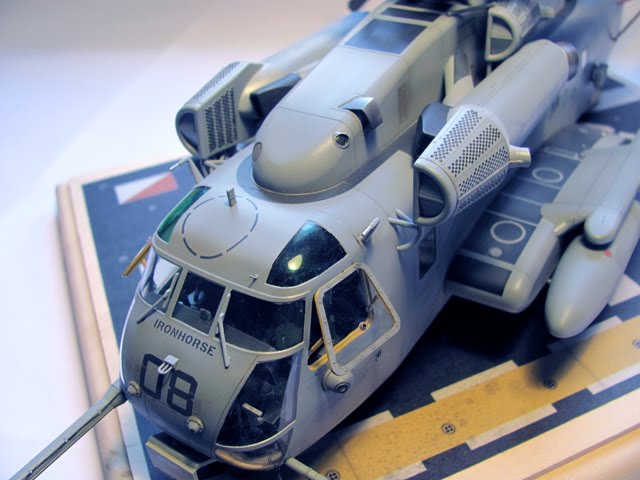
 The engine intake cowling thing has a lot of black round things on it. I don't know what those are, but based on reference pictures, I painted them black, one at a time. It was such a painstaking process because there are 3 of such intakes (because of the 3 engines). I then dry brushed light grey over them to tone them down a little.
 As you can see below, the cockpit is pretty visible, so make sure more attention is paid to it.
 I should have painted more flat clear over the blades. Ah well...


The support beam for the rotor blade was hand painted red and then dry brushed with silver to mimic paint chipping.

The cockpit area was also heavily dry brushed with light grey to make it stand out more.


Below is a picture of the real thing. Picture copyright of Peter Tonna. Photo from Airliners.net


 Don't bother too much on the detailing the interior of the cabin. Nothing much can be seen when the model is put together anyway. However, attention should be paid to the cockpit, as this part is more visible.


I should have added more detail at the tail fold section. Well, maybe next time.


 This helicopter is a huge beast.

3 comments:
thanks for sharing your build. You did an AMAZING job! I love it! I'm considering building one. Now I have lots of pointers and look forward to it. Thanks again
I'm a ch53 crew chief and its not bad for a kit, def lacking in detail at some places, especially at the tail disconnect and rotor head, but oh well...great job
I built the engines for these, The cones on the front of the engines are particle separator's, the were used to separate dust and sand before it entered the intake of the engines, they could be electronically opened and shut, and had a belt driven blower that ran off of the gear box.
Post a Comment